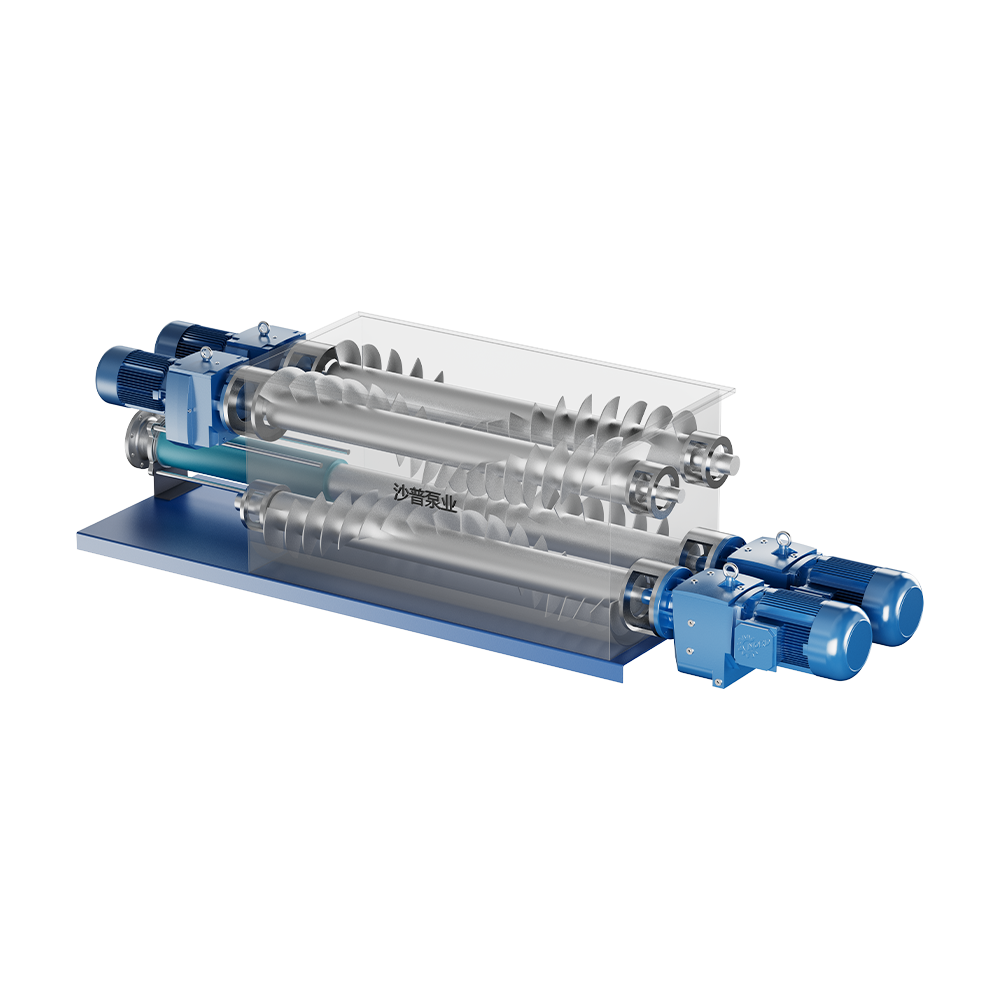
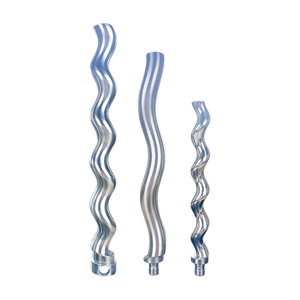
progressive-cavity-pump-rotor
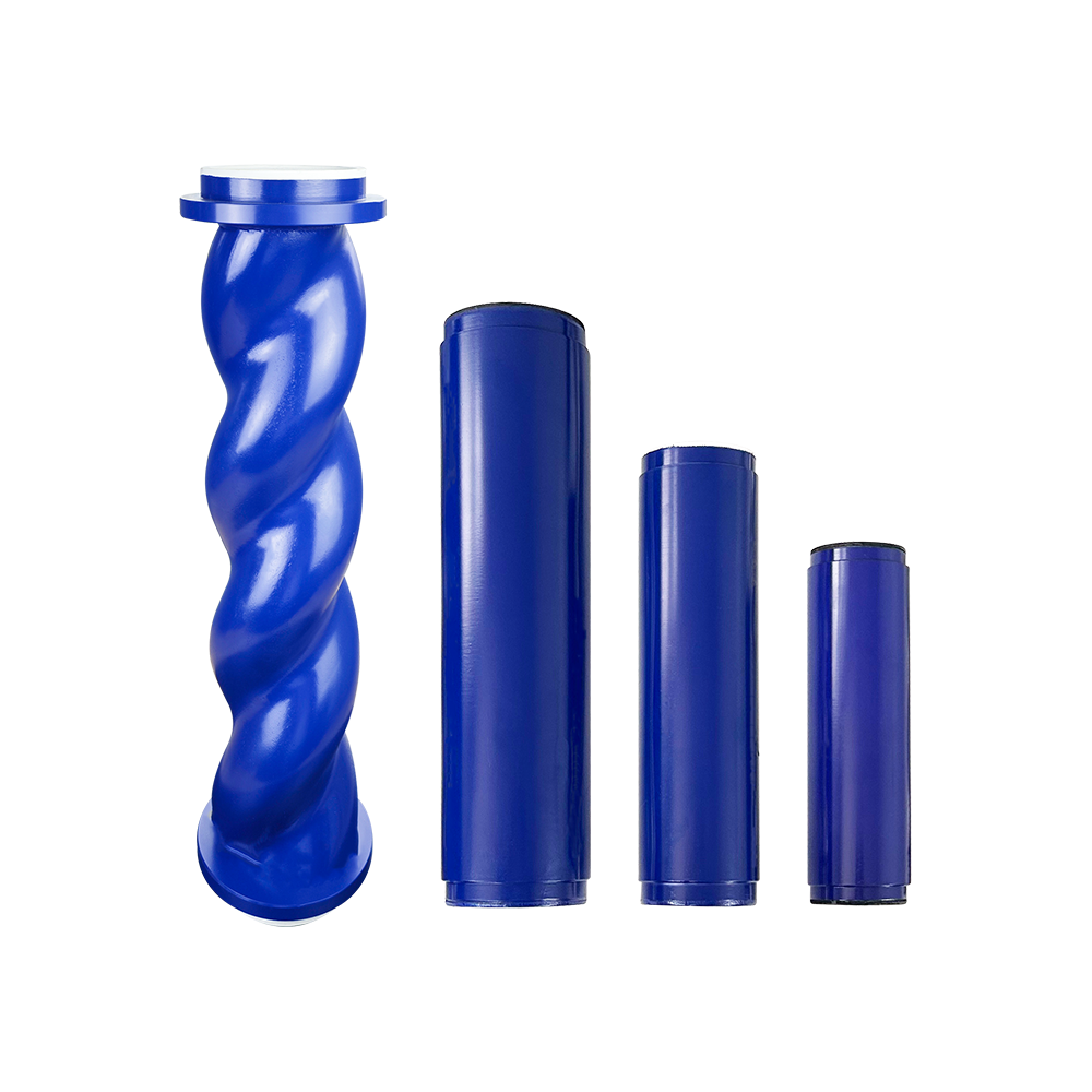
progressive-cavity-pump-stator
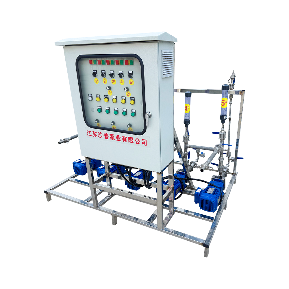
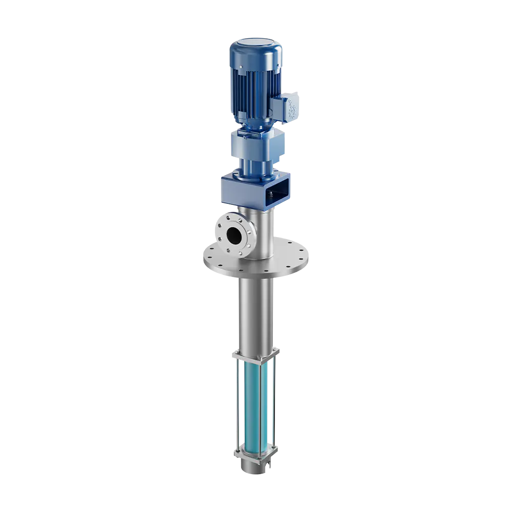
pump-system
Content
A progressive cavity pump is a positive displacement machine that moves fluid through a series of sealed cavities formed between a helical rotor and a double-helix stator. Because it is also known as a single screw pump, both names appear frequently in technical catalogues and procurement documents, and they describe the same working principle. Plants choose this design when the medium is thick, contains solids, or must be transferred without shearing or foaming. Typical users include wastewater treatment facilities, food manufacturers, chemical producers, and mining operations.
Understanding how this pump works, how it compares with alternatives, and which operating data must be defined before selection will help engineers, maintenance planners, and purchasing teams reach a sound decision. This article follows that sequence so that every stakeholder can use the same reference when discussing a project.
The working principle is simple but effective. A metal rotor with a single external helix turns eccentrically inside a stator whose internal bore has a double helix, usually molded from elastomer. Where the two components meet, they form a series of sealed chambers. As the rotor turns, these chambers advance axially from the suction side toward the discharge side, carrying the fluid with them. Because the cavities move continuously rather than in pulses, the discharge flow is smooth and largely free of the pressure spikes common in reciprocating designs.
Each cavity opens at the inlet, travels along the stator, and closes at the outlet. The volume transferred per revolution is set by the geometry of the pumping elements, so flow rises almost linearly with speed. This makes the pump easy to control with a variable frequency drive.
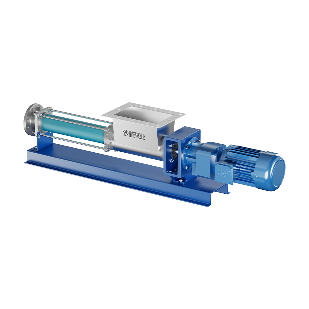
The diagram shows how the rotor sits within the stator and how suction and discharge sit at opposite ends. Flow moves in one direction without internal valves, which is one reason the design tolerates solids that would jam valve-based pumps.
Selection rarely depends on a single feature. Engineers usually weigh several characteristics together, and the list below reflects the points that most often decide a specification.
| Pump Type | Pulsation | High Viscosity | Solids Handling | Shear Sensitivity | Dry Running |
|---|---|---|---|---|---|
| Progressive cavity | Low | Excellent | Good | Gentle | Limited |
| External gear | Low | Good | Poor | Moderate | Limited |
| Lobe | Low to moderate | Good | Good | Gentle | Limited |
| Diaphragm | High | Moderate | Fair | Gentle | Good |
| Centrifugal | Low | Poor | Moderate | Harsh | Poor |
The comparison shows why the design is often chosen for demanding fluids. It is not the lowest-cost option for thin, clean liquids, but it becomes competitive quickly as viscosity and solids content rise.
Application fit depends on the medium, the duty cycle, and the plant environment. The following sectors represent the most common uses and the reasons the pump is selected in each.
Practical tip: when a fluid contains large or fibrous solids, confirm the hopper or feeder requirement early. Inlet design often determines whether the pump runs smoothly in the field.
A reliable selection starts with complete process data. Missing or approximate values are a common cause of premature wear and disappointing performance. Engineers typically work through the following parameters before comparing models.
Working through the parameters in this order keeps the discussion focused. Each step narrows the options, and the final specification sheet becomes the basis for both engineering review and commercial evaluation.
Because the rotor and stator form the pumping element, they are the components that wear. Their service life depends heavily on the medium. The figures below are indicative only and reflect the general ranges reported in industrial practice. Actual life should be confirmed through trial operation or plant records.
| Service Condition | Indicative Stator Life | Indicative Rotor Life |
|---|---|---|
| Clean, low-abrasion fluid | Several thousand hours | Long, often exceeding stator life |
| Mildly abrasive sludge | About 2,000 to 5,000 hours | Long, with periodic inspection |
| Heavy abrasive slurry | About 500 to 2,000 hours | Moderate, depends on coating |
| Chemically aggressive medium | Highly variable | Depends on coating and compatibility |
A structured maintenance routine reduces unplanned stoppages. Plants that track flow, pressure, and power trends can often detect stator wear before it affects output. Keeping a matched set of rotor, stator, and seal kits on site shortens downtime, and planning for progressive cavity pump spare parts early in the project avoids long procurement delays later.
Most premature failures trace back to a small set of operating errors. Recognizing them early makes them easier to prevent.
Good practice: record the stator fit, speed, and fluid temperature at commissioning. This baseline makes later troubleshooting far faster.
A quotation is only as accurate as the data behind it. Engineering teams can respond faster and with fewer clarifications when the request includes complete operating information. The following list covers the details that most often speed up review.
When these items are provided together with the expected duty cycle, the engineering review can focus on matching the pump geometry and materials to the process rather than on requesting missing information.
Cost depends on capacity, discharge pressure, body and rotor materials, elastomer compound, seal arrangement, and any feeder or drive requirements. Customized duties usually require additional engineering time, so providing complete process data is the most reliable way to obtain a realistic quotation.
Short dry-run events are sometimes tolerated, but sustained dry running damages the stator quickly because the elastomer loses its lubrication and cooling. Dry-run protection, such as a level switch or pressure monitoring, is recommended for any installation where the supply can be interrupted.
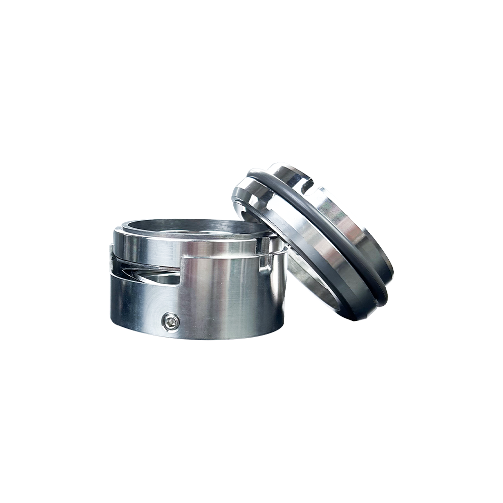
The stator usually wears first, particularly in abrasive service, because its elastomer surface is in continuous contact with the rotor. The rotor wears more slowly, and the mechanical seal and universal joint are typically inspected at the same time.
Very thin, clean liquids that do not need positive displacement are better served by simpler pumps. Fluids that attack the elastomer chemically, or that contain large hard objects that can jam the rotor, also require careful evaluation or pre-screening.
Inspection intervals depend on the medium and duty cycle. Abrasive or high-temperature services often call for checks every few months, while cleaner applications may allow longer intervals. Monitoring flow and motor current helps refine the schedule over time.
Yes. Customization commonly covers elastomer compounds, rotor coatings, seal arrangements, hopper designs, and drive configurations. Providing drawings or sample data at the start allows the engineering team to propose a configuration that matches the process requirements.

 maoyaojunyfc@sppump.cn
 +86-523-84231792










 русский
 Español
 عربى
 中文简体